
Schukat
Protected against transient overvoltages
In industrial applications, it is important to protect systems and devices from transient overvoltages. These can damage electronic components and cause downtime. Surge protection devices can prevent failures and therefore high costs.
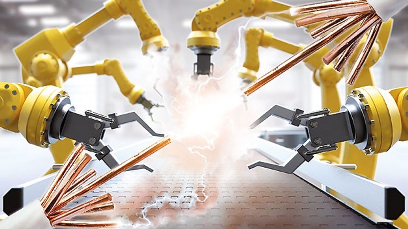
Overvoltages caused by lightning strikes or switching operations are commonplace. However, developers and operators of industrial electronic components and systems are faced with the challenge of protecting the systems used against short-term voltage peaks, i.e. transient overvoltages. The reason for this is complex technical systems with ever smaller, more powerful devices that are growing in their range of functions and thus becoming even more vulnerable. The switching power supplies used in industrial systems, for example, have a high dielectric strength, but the power supply is often unable to dissipate the high pulse energy caused by transients adequately or at all. Many power supply failures in the field are due to overvoltages.
Increasing industrial automation is increasing the number of potential sources of interference and products susceptible to faults, while the trend towards ever smaller systems is also reducing the spatial distance between components. In the course of Industry 4.0, the system components for data exchange are also becoming more networked: Data transmission networks are growing and plant components are increasingly exposed to interference. Data lines also pose a high risk of failure due to coupled surges without adequate protection.
How do surges occur in an industrial environment?
Transient overvoltages mainly occur as a result of lightning strikes (LEMP, Lightning Electro Magnetic Pulse), but even more frequently due to switching operations of connected electrical components (SEMP, Switching Electro Magnetic Pulse). The overvoltages that occur differ in amplitude, duration and frequency.
Due to the high short-term energy discharge during a lightning strike, strikes in the immediate or distant vicinity are sufficient to damage electrical systems. When lightning strikes overhead lines, high surge voltages build up, which continue along the line and eventually reach connected devices. In a system that is connected to several earthing points, a lightning strike causes a high potential difference. This means that the devices connected to the affected networks can be destroyed or their operation severely impaired.
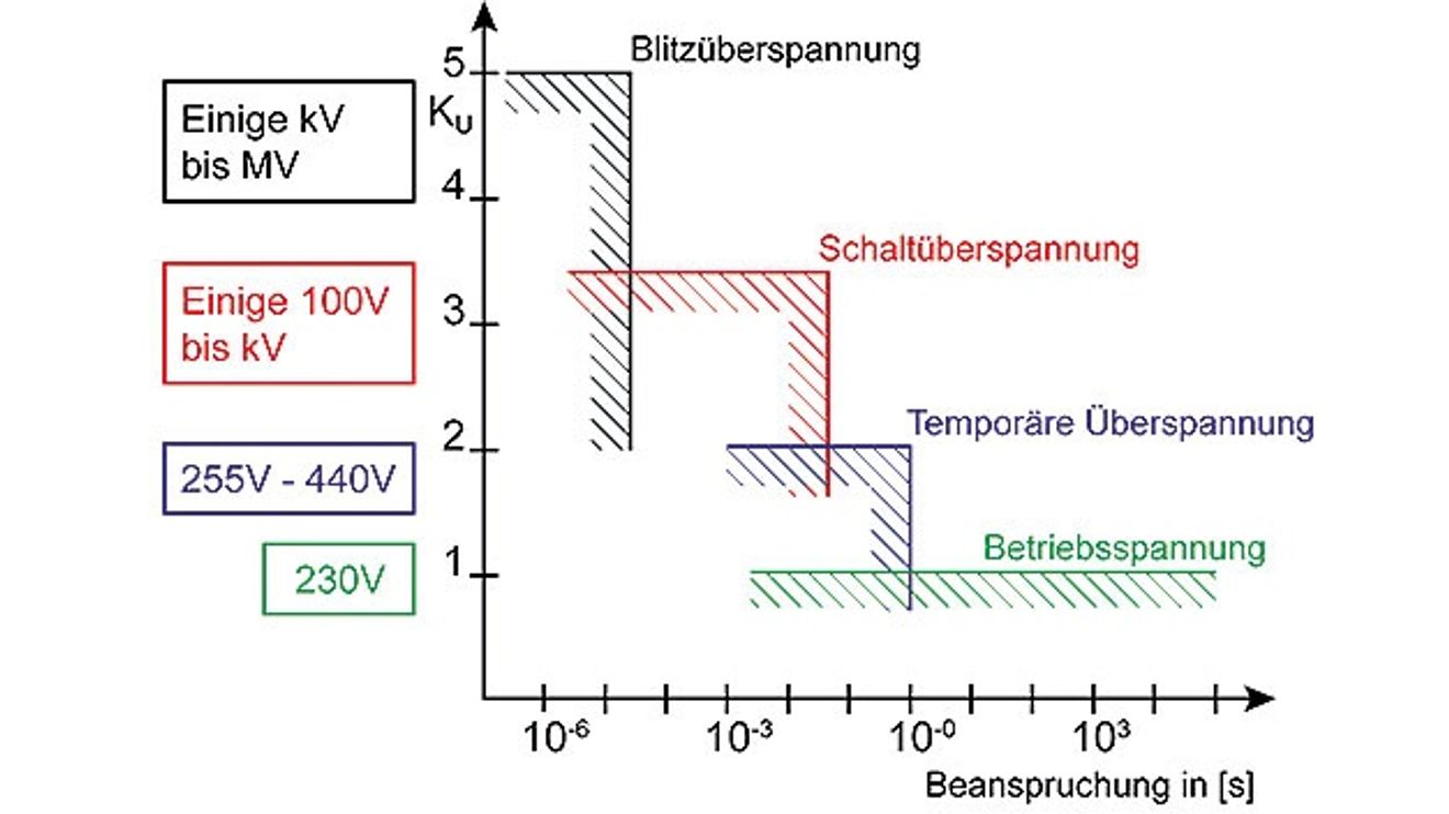
Although with a lower energy intensity than lightning strikes, surge voltages caused by switching operations occur much more frequently. These phenomena are caused by switching electrical energy sources on or off. In industrial systems, for example, they occur when motors are started or transformers are switched on, but also when other inductive loads are switched, large capacitive loads are switched, fuses and circuit breakers are tripped or power lines are dropped. In contrast to temporary overvoltages of a few seconds with a few hundred volts, these cause transients of up to 6 kV with rise times in the order of a few microseconds. (Figure 1) They disrupt the operation of devices and can occur several hundred times a year in electrical installations.
Consequences of and protection against overvoltages
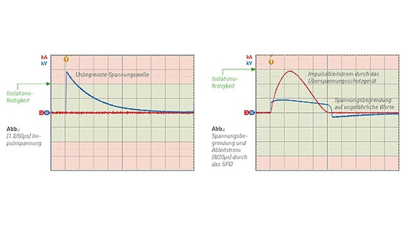
Figure 2: Unaffected overvoltage (left) vs. applied overvoltage with active protection by means of SPD (right).
© Schukat/CitelTransient overvoltages affect electronic devices in various ways and with varying degrees of intensity. In the absence of hardware damage, they can lead to a temporary malfunction or undefined operation of the system due to data or transmission errors, as well as causing program crashes or the deletion of memory contents. In the worst case, the hardware may be destroyed due to a voltage breakdown of semiconductor junctions, destruction of the bonding wire connections of components or the conductor tracks. In the event of a hardware defect, additional service costs are incurred and the system downtime lasts longer. In both cases, however, restrictions or downtimes are to be expected.
If only minor overvoltages occur as a result of the switching processes described, they may not directly damage the connected devices. However, they stress the electronic components installed in the devices and result in premature ageing and therefore shorter operating times.
Surge protective devices (SPDs) offer effective protection. The term generally applies to all devices that protect against voltage peaks. In order to achieve adequate protection, the components must be selected according to the risk and installed in compliance with applicable standards. The requirements and tests for SPDs for low-voltage systems are set out in national and international standards such as EN 61643-11 and UL 1449.
How does a surge protective device work?
As a safety element of the system, the SPD protects the system against transient overvoltages without any faults. Surge protective devices are generally based on varistors or gas-filled spark gaps or a combination of both. The latter represents the best possible compromise between the most important features for efficient surge protection, namely a fast response time of less than 25 ns and the highest possible leakage current. The maximum leakage surge current for surge protective devices is the maximum surge current with 8/20 µs pulse. A surge protective device can withstand this without being destroyed. The rated leakage surge current is the value of the surge current that a surge protective device can withstand several times without being destroyed. In the event of an applied overvoltage, the SPD discharges the energy and reduces the maximum residual voltage to a defined protection level (Figure 2).
The protection level of the surge protective device must be selected so that it is matched to the dielectric strength of the devices to be protected. A basic distinction must be made between coarse, medium and fine protection. The lower the protection level, the better the surge protection. The IEC 60364 standard specifies a maximum protection level of 2.5 kV for surge protection devices used at the input of 230 V or 400 V networks. This value corresponds to the dielectric strength of robust electromechanical devices and should be reduced as far as possible by means of fine protection.
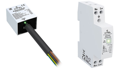
Figure 3: Surge protection devices for different connection and mounting types: MLPCA1 series from CITEL for IP67 flash connection (left) and DACN10 from CITEL with spring-cage terminals for DIN rail mounting (right).
© Schukat/CitelIn addition to the protection for the 230 VAC or 400 VAC supply lines, the protection of the data and control lines must also be taken into account in networked systems. Damaging overvoltages can also couple onto data lines and the dielectric strength of the interface modules can be relatively low. Coarse or medium protection installed at the feed-in point, which is also prescribed for new industrial systems, is often not sufficient on its own. For cable lengths of approx. 10 m or more to the end device, for systems in industrial environments and especially for outdoor operation, a type 2 or type 3 arrester or a combination of both directly on the end device or in the associated switch cabinet is recommended. SPDs are available for mounting on the top-hat rail as well as for installation in the end system with stranded wires, plug-in or screw connection (Fig. 3).
The SPD protects the device regardless of the level of overvoltage. If the pulse energy exceeds the discharge capacity of the protective element, it may be overloaded, but the end system is still protected in this case.
In accordance with the standards, surge protective devices must also be equipped with an internal and an external disconnecting device, which provide the best possible protection for the connected electrical applications in the event of a fault.
Overview of SPD types |
|---|
|
Surge protective devices are classified into type 1, 2 and 3 according to the standards mentioned: - Type 1 - lightning current arrester: Depending on the design, they are used in the pre-metering area or directly behind it, where the highest currents are to be discharged in the event of a direct lightning strike. - Type 2 - Surge arrester: These arresters are used in the main or sub-distribution board of the electrical installation and protect the downstream lines and electrical applications by suppressing current pulses as quickly as possible. - Type 3 - Surge protection: These arresters are used in the immediate vicinity of sensitive electrical or electronic end devices. They reduce the overvoltage already reduced by type 2 arresters to an acceptable level for commercially available end devices. - Combined arresters that cover several categories are also available, such as type 1+2 or type 2+3, which can also be used directly on or in the immediate vicinity of the end device, as well as type 1+2+3, which combines all three categories in one SPD. |
As an indispensable safety element, the internal thermal disconnection device disconnects the surge protective device from the mains in the event of a fault or overload. The operator is then notified via the fault signaling of the arrester to replace the corresponding protection module. The user must provide protection against a short-circuit current in each SPD feeder. The manufacturer specifies the tripping current of this fuse in the product data sheet and the installation instructions.

The author: Frank Stocker is Field Application Engineer Power Supplies at Schukat electronic.
© Schukat/CitelThe external electrical disconnecting device, usually a fuse or a circuit breaker, safely disconnects the surge protection device from the mains in the event of a short circuit. Some surge protection devices are available in a version with remote signaling. The potential-free changeover contact is used for status monitoring and can be integrated as a binary output in modern networked industrial systems, for example, in order to monitor the operating status and proper function.


You might also be interested in
Peak power of 200 %
The industrial switching power supplies of the 'HRP-N' series from Mean Well expand Schukat's power supply portfolio. HRP-150N, HRP-300N and HRP-600N have an output of 150, 300 and 600 W respectively.
 read more...
These are your winners!
We put 96 products in twelve categories to your vote in December, and now the winners have been chosen! The trophies were presented at a 'Winner's Dinner' at the Seehaus in Munich. These are your "Products of the Year 2024"!
read more...Three trends in cybersecurity developments
Cybersecurity is once again at the top of most companies' IT agendas this year. The potential threats include not only session hijacking and credential theft, but also the technical consolidation of existing security systems.
read more...These are the AI trends for 2024
Artificial intelligence is changing the entire IT world forever and is having a huge impact on how data is understood, analyzed and used. AI is also taking data management to a new level. Five AI trends have been identified for the year 2024.
read more...Automation has no place for racism!
Racism is closer than you think. A reason to show your colors!
read more...THE OFFICIAL DAILY - The three-pack 2023
All issues of THE OFFICIAL DAILY, the official trade fair newspaper for SPS, at a glance. The issues of all three publication days, packed with news and trends from the automation industry, are available as an e-paper with additional interactive...
read more...New product line for mechanical engineering
At SPS 2023, Synapticon presented the completely new 'Somanet Integro' product line for the first time, which marks the company's entry into a new market segment: general mechanical engineering.
read more...Free IIoT software
The first step in IIoT projects is usually the digital connection and subsequent configuration of the devices - for example with IO-Link devices and the 'moneo configure' software from ifm. This is now available free of charge.
read more...I/O electronics with X possibilities
"An I/O system as versatile as our customers," is how Sigmatek Managing Director Alexander Melkus describes the 'ready to use' I/O system 'X-DIAS' from Sigmatek, which celebrated its premiere at the trade fair.
read more...