

Fischer Connectors
Layer by layer
In the course of the growing demands on data communication in the IoT age, the connector geometry, among other things, must be rethought when assembling high-speed connectors for an optimal energy flow. What needs to be taken into account?
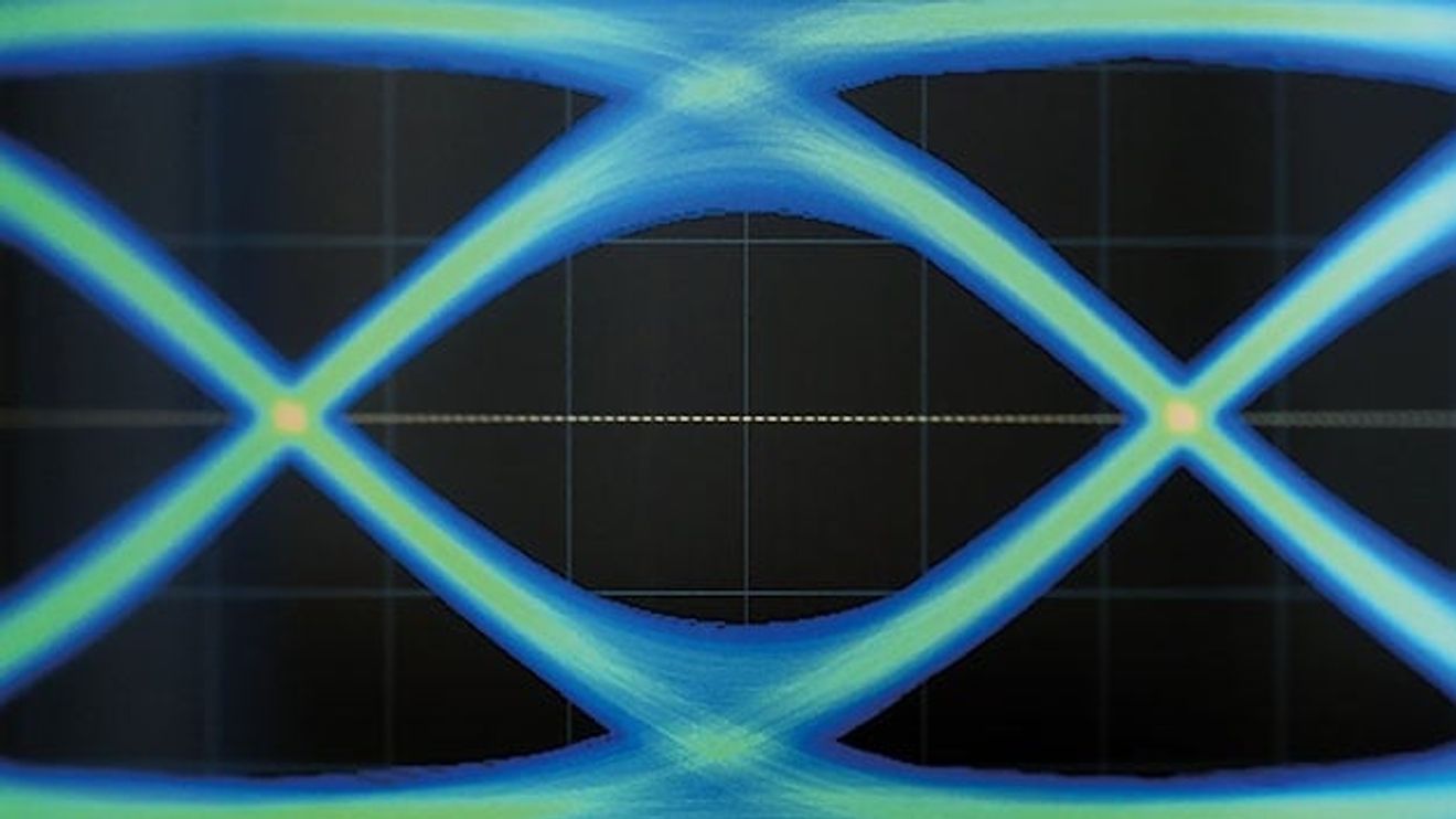
High-speed data transmission - the backbone of IoT and Industry 4.0 - stands and falls with high-performance and reliable connection technology. This is because unfavorable phenomena such as noise, distortion and insertion loss can impair signal transmission, especially when transporting data over long distances. Each design must therefore be optimized mechanically, electrically and in terms of EMI and EMC shielding.
The quality and speed of a connection depend on many factors, not least the performance of the transmitter and receiver. It is not for nothing that the specifications of the transmitter and receiver make up a lion's share of the USB 3.0 specifications. As a general rule, higher data transfer speeds require higher signal frequencies. Due to these higher frequencies, special physical phenomena occur at the connection point between the data transmitter and the connector, which do not have to be taken into account in designs for lower transmission speeds.
A question of geometry
With high-speed data connections, the maximum required frequency (fmax) of a signal is very high in relation to the distance it has to travel. In addition, the current is transmitted from one side of the connector to the other not only via the metallic surface of the pins, but also via the polarization of the dielectric. Accordingly, when designing high-speed connection technology, engineers cannot limit themselves to the direct current conductivity of metallic surfaces alone, but must also consider the influence of the dielectric materials.
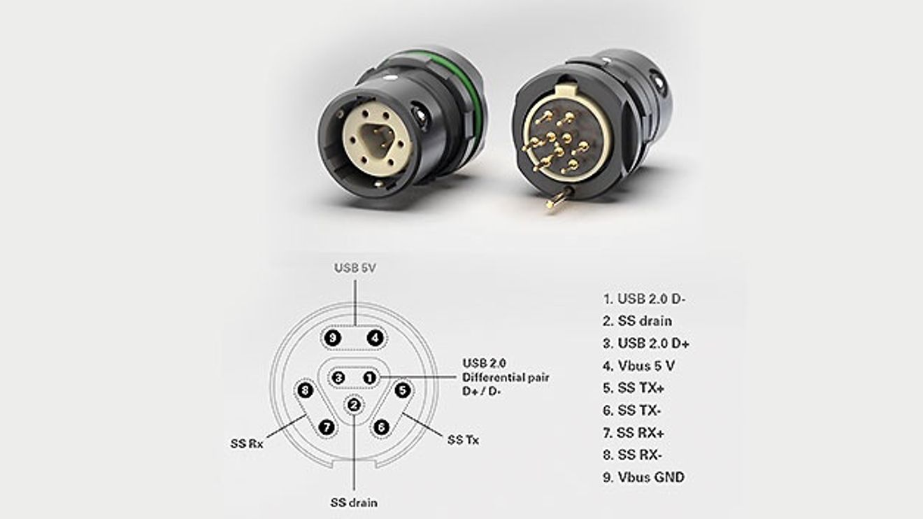
The main cause of signal loss in cables is insertion loss, i.e. the loss of energy during signal transmission via a cable connection. With connectors, on the other hand, reflection losses are the main concern: if the input impedance of the transmitter differs from the input impedance of the connector, part of the input energy is reflected in the direction of the transmitter. Part of the remaining energy is lost due to metallic or dielectric losses in the connector, the 'rest' reaches the other side, i.e. the receiver. Material and geometry have a direct effect on the impedance.
Specifications of the physical layer
The OSI reference model distinguishes between seven successive layers in data communication:
- Physical layer
- Data link layer
- Network layer
- Transport layer
- Session layer
- Presentation Layer
- Application layer
The overall speed of a communication system on the data transmission layer depends on its architecture and the specifications of the sender and receiver. The data link layer above the physical layer is responsible for detecting any bit errors and correcting them if necessary.
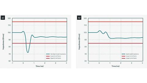
The measured TDR impedance response of a non-optimized connector (left) compared to that of an optimized connector (right).
© Fischer ConnectorsNormally, a total bit error rate (BER) of 1e-12 is tolerated in the bit transmission layer. In order to achieve the required BER, standards specify certain parameters for cable and connector assembly that influence the quality of data transmission. These include, among others:
- Impedance curve: usually measured with a Vector Network Analyzer (VNA) or a Time Domain Reflectrometry device (TDR) and expressed as a ratio of V/I or E/H
- Power delay: latency of signal propagation
- Insertion loss and return loss: attenuation and mismatch
- Coupling inductance (IC): allows connectors to be modeled as both a source or sink of interference, expressed in Henry
- Crosstalk level (depending on the type of interference, near-end crosstalk, NEXT for short, or far-end crosstalk, FEXT for short): field coupling between the channels within a cable, depending on the signal and ground assignment of the channels
- Losses during mode conversion
- Shielding: interference by and from surrounding devices
- Integrated parameters: arise from the interaction of several parameters
Design tips
From this knowledge of the factors influencing the quality of high-speed data transmission, some tips can be derived for the successful design of connector-cable assemblies. For example, a material with high conductivity proves to be advantageous in contact design. The conductivity results from the specific resistance of the metal, but the crystalline structure of the metal (the more ordered, the better the conductivity) also plays a role here. Silver, copper and gold have particularly good conductivity.

The author: Martin Wimmers is Managing Director of Fischer Connectors in Zorneding.
© Fischer ConnectorsThe relative dielectric constant of the insulating material (nowadays better known as permittivity) should also not be ignored. Fluoropolymers, for example, are known for their good electrical and dielectric properties, whereas PVC is not recommended as an insulating material, especially in high-speed applications. The topic of EMC should always be at the forefront of the design, as it starts with the choice of material and questions of connector geometry such as the number of contact points. The aim here is to reduce the magnetic field created by the dissipation of the interference current in the environment as much as possible - for example by splitting the current flow using multiple contact shielding plates. Ground channels can act as a 'buffer' between the individual signal channels to reduce the influence of these on each other, especially crosstalk.


You might also be interested in
Getting to the bottom of cable asymmetry
Many faults in industrial networks and systems are caused by electromagnetic compatibility (EMC). However, it is often not known exactly what these are - such as interference currents due to asymmetrical supply lines.
 read more...
Ex cable gland program expanded
The 'LevelEx' Ex d cable glands from Pflitsch offer a compact design, captive parts and a range of applications for Ex d, Ex e and Ex t equipment class II in the areas of gas and dust.
read more...Flexible wire assembly
At SPS 2022, Rittal presented the 'Wire Terminal WT C5' and 'C10' fully automatic wire assembly machines, with which wires can be assembled ten times faster than by hand with individual wire printing (black, white and light blue) and order picking,...
read more...A positive start to the 2nd half of the year
The electrical and digital industry recorded double-digit growth in incoming orders in the first half of the year, according to the ZVEI In June, however, only a slight increase of 0.5% was recorded compared to the same month last year.
read more...EMC connectors for drive systems
Ilme launches compact EMC connectors for drive technology.
read more...One Cable for M16, M23 and M40
Hummel presents hybrid connectors in the M16, M23 and M40 series, including the M23 Hybrid Type 2 (4+4+4+PE) with four power contacts.
read more...Installing and routing multiple cables in an EMC-compliant manner
Pflitsch has expanded its UNI Dicht modular system to include the 'UNI Dicht Mehrfach TRI' for EMC applications in order to install several cables in one cable entry to save space.
read more...Exports above pre-crisis level
The German electrical and electronics industry significantly increased its exports in the first half of 2021 and exceeded pre-crisis levels.
read more...Material bottlenecks impact mechanical engineering
The shortage of materials is hampering production in the German mechanical engineering sector. Despite these circumstances, the VDMA does not believe that its sales forecast is at risk.
read more...