

E-T-A
Optimally secured
A central element of planning for 24 V (DC) circuits is the protection of a wide variety of loads against overcurrents. Choosing the right fuse protection is anything but trivial. An overview.
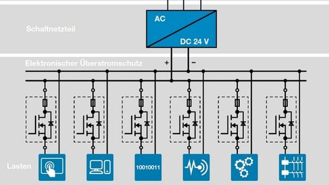
Consumers and cables in 24 V (DC) circuits must be protected against damage or even destruction due to overcurrents. Optimum protection also enables the targeted disconnection of faulty loads or load paths only. Thanks to this selectivity, a single fault does not lead to an unwanted failure of the entire 24 V (DC) voltage and troubleshooting is also accelerated.
When taking a closer look at a typical 24 V (DC) circuit, it quickly becomes clear that it is not always easy to select the right fuse, as various factors - from the voltage source and the cables used to the wide variety of loads that need to be protected - interact with each other. In addition, the large number of available fuses and their different modes of operation make the choice difficult.
Classically secured
To understand where the current challenges in protecting 24 V (DC) loads come from, it is necessary to take a brief look at the past of the 24 V (DC) structure. Originally, 24 V (DC) control voltages were generated using transformers and rectifier circuits. The transformer converted the voltage applied on the primary side, for example 230 V(AC), into a lower AC voltage; the rectifier circuit then converted the lower AC voltage into a DC voltage.
The classic protection for such a setup is a standard circuit breaker. Its thermal-magnetic mode of operation makes it possible to provide good protection for two different fault patterns. In the event of low to medium overcurrents, the bimetal responds after a few seconds and disconnects the faulty circuit. In addition, this thermal tripping principle enables the safe switching on without premature disconnection of power-intensive loads, loads with high inrush current peaks (such as DC motors or valves) and loads with a high capacitive component. In the event of high overcurrents - such as a short circuit - the solenoid coil disconnects the load circuit within a few milliseconds. For a long time, miniature circuit breakers in combination with transformers were the standard protection for 24 V (DC) load circuits.
However, the described process for generating 24 V(DC) had the disadvantage that transformers were relatively heavy and expensive and often did not have good efficiency.
Problems
The increasing use of switched-mode power supplies has also changed the problem of 24 V (DC) protection. Unlike classic transformers, switched-mode power supplies have a comparatively low overload capacity. Due to this 'power limitation' of the voltage source, it is no longer possible to use thermal-magnetic fuses without further ado, as the limited current available in the event of a fault is not always sufficient to trigger the solenoid coil.
The bimetal only disconnects after a few seconds, which results in a complete failure of the 24 V (DC) voltage. To protect themselves from an overload, almost all switching power supplies reduce the output voltage after just a few milliseconds or switch off the secondary side completely. Long load cables even exacerbate this problem, as excessive line resistance further limits the current available in the event of a fault.
There are various ways of dealing with this problem: One solution is to keep the power reserves available in order to provide a sufficiently high current in the event of a fault. Another option is to select circuit breakers with a faster characteristic curve. However, additional power reserves are more expensive and require more space in the switch cabinet. Faster circuit breaker characteristics increase the risk of unintentional tripping, especially when connecting loads with increased inrush current.
Modern protection
Electronic protection solutions are therefore increasingly being used. Electronic overcurrent protection offers a number of advantages compared to classic miniature circuit breakers and other thermal-magnetic devices - especially when used together with switching power supplies. The electronic characteristic curves of devices such as the REX12 or the ESX10-T from E-T-A are specially designed for the power characteristics of switched-mode power supplies and thus enable fast and targeted disconnection in the event of a fault. There are two different approaches and modes of operation: active current limiting and the time-current characteristic.
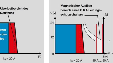
With the time-current characteristic approach, the load circuit is disconnected after less than 1 s in the event of a low to medium residual current. This allows most loads and load types to be switched on, as overcurrents are tolerated for short periods of time. A longer lasting overcurrent leads to disconnection by the electronic overcurrent protection.
In the event of high residual currents, the electronic overcurrent protection triggers within 10 ms and is therefore fast enough to prevent the switched-mode power supply unit from being switched off unintentionally.
The active current limitation in the ESX10(-T), REF16 or ESS30 and ESS31-T devices follows a different approach: At low to medium overcurrents, this technology behaves very similarly, shutting down within a few seconds. With high overcurrents, on the other hand, active current limiting intervenes. This means that the fault current is limited to a defined value and switched off within 1 second. This guarantees that the power limits of the switching power supply used are not exceeded.
Even with extreme starting currents, there is no problem with premature tripping, as the current limitation enables a comparatively slow switch-off time. In addition, planners can calculate each fault and thus determine how much power the application requires.
Which technology is suitable and when?
It is not possible to assign 100% of the different consumers to a specific protection technology. Rather, there are certain characteristics of loads that must be taken into account when selecting a fuse protection solution. Most standard loads can easily be protected with a time-current characteristic and with active current limiting. If the power supply is dimensioned accordingly, thermal-magnetic solutions can also be used.
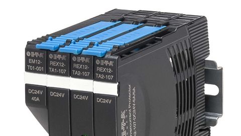
Thanks to its user-friendly connection technology, the REX12 system can be assembled and wired modularly and without accessories.
© E-T-AHowever, this is only possible if it can be ensured that the current available in the event of a fault is sufficient for magnetic tripping. With very long load lines, the supply lines act as an additional current limiter. Electronic fuses should preferably be used here, which also trip reliably with a limited fault current. Active current limiting is best suited for loads with a high current requirement at the moment of switch-on , as it tolerates all current peaks for a comparatively long time and can therefore switch on even extreme inrush currents safely. The time-current characteristic is also suitable, but should be matched more precisely to the load requirements. If loads have integrated voltage monitoring on the input side, a time-current characteristic is the best solution, as the voltage for the load is not affected.
Special features of standardization
In Germany, Europe and North America, EC/EN 60934 and UL 1077 define the requirements for circuit breakers. They ensure that the function, behavior and safety of circuit breakers meet uniform criteria. According to these relevant standards, galvanic isolation is also mandatory for 24 V (DC) load circuits in the event of a fault. At the same time, galvanic isolation offers further advantages in addition to compliance with these standards: it prevents fault-related feedback to the 24 V (DC) control voltage level after tripping or manual disconnection. This completely eliminates dangerous system states and also enables simplified troubleshooting without residual voltages.

Marco Schmidt is a Junior Product Manager in the Automation & Process Control division at E-T-A in Altdorf.
© E-T-AIn order to meet these requirements, there are corresponding devices that allow galvanic isolation in addition to the electronic characteristic curve. In the ESS30 and ESS31-T devices, a fully-fledged bimetallic module is integrated, which provides electrical isolation in the event of a fault. In the event of an overcurrent, the load circuit is switched off electronically first and a few seconds later the mechanical isolating element also disconnects.
Many machines and systems from the EU are supplied to North America. For use in these countries, it is necessary for the components to be UL-certified. For example, switch and control cabinets must be designed in accordance with UL508A (Industrial Control Panel). Electronic circuit breakers without integrated galvanic isolation have UL508listed (Industrial Control Equipment) or UL2367 (Solid State Overcurrent Protector) approval as standard. For some circuit breakers up to a rated current of 4 A, UL2367 can be supplemented by UL1310 approval (Class 2 Power Unit NEC Class 2). This means that these devices can also be used in secondary circuits in accordance with UL508A. Due to the 'listed' approval, a 'procedure description' is not required.


You might also be interested in
Implementing intrinsically safe circuits
The 'Ex i' type of intrinsic safety has become established worldwide for measurement and control technology in systems with potentially explosive atmospheres. Compared to other types of protection, it is more cost-effective in terms of design.
 read more...
Fanless 600 W power supply for industrial applications
XP Power is launching a convection-cooled 600 W power supply series on the market, targeting medical, ITE and industrial applications.
read more...The new e-paper is here
The term Industry 4.0 has characterized the development of automation technology since the Hannover Messe 2011. The ultimate goal is the smart factory. Today, we are a good step further, because the Industry 4.0 concept is now being implemented.
read more...Integrated digital monitoring functions
Powerbox has announced a power supply solution for immersion cooled data center applications.
read more...Connection to the cloud
ABB launches a Bluetooth-equipped power quality analyzer for electrical measurement and power monitoring of all installations. The M4M can perform a complete power quality analysis and accurate energy monitoring.
read more...DC/DC converter with wide-range input
Bicker Elektronik presents the 'DC300WS', a contact-cooled 300 W DC/DC converter with up to 98 % efficiency.
read more...22.5 mm wide electronic circuit breaker
The electronic 4-channel circuit breakers (ECBs) 'Pisa-M' from Puls are aids for protection and power distribution in applications with power requirements from 90 W to 480 W.
read more...3-phase power supply delivers 3.5 kW
Cosel launches the 'HFA3500TF', a flat, three-phase, three-wire, closed 3500 W AC/DC power supply optimized for industrial equipment such as semiconductor manufacturing, laser processing machines and robotics.
read more...Power supply for high-performance computer systems
The ATX power supply units of the 'Delta GPS' series from Bicker are suitable for high-performance computer systems and graphics-intensive applications.
read more...