

Analog Devices
A Framework for modern Robot Applications
The ROS1 driver for Trinamic motor controllers from Analog Devices enables the seamless integration of intelligent actuators into ROS-supported robot systems. This article describes features, configuration options and application scenarios for robust use in industry and research.
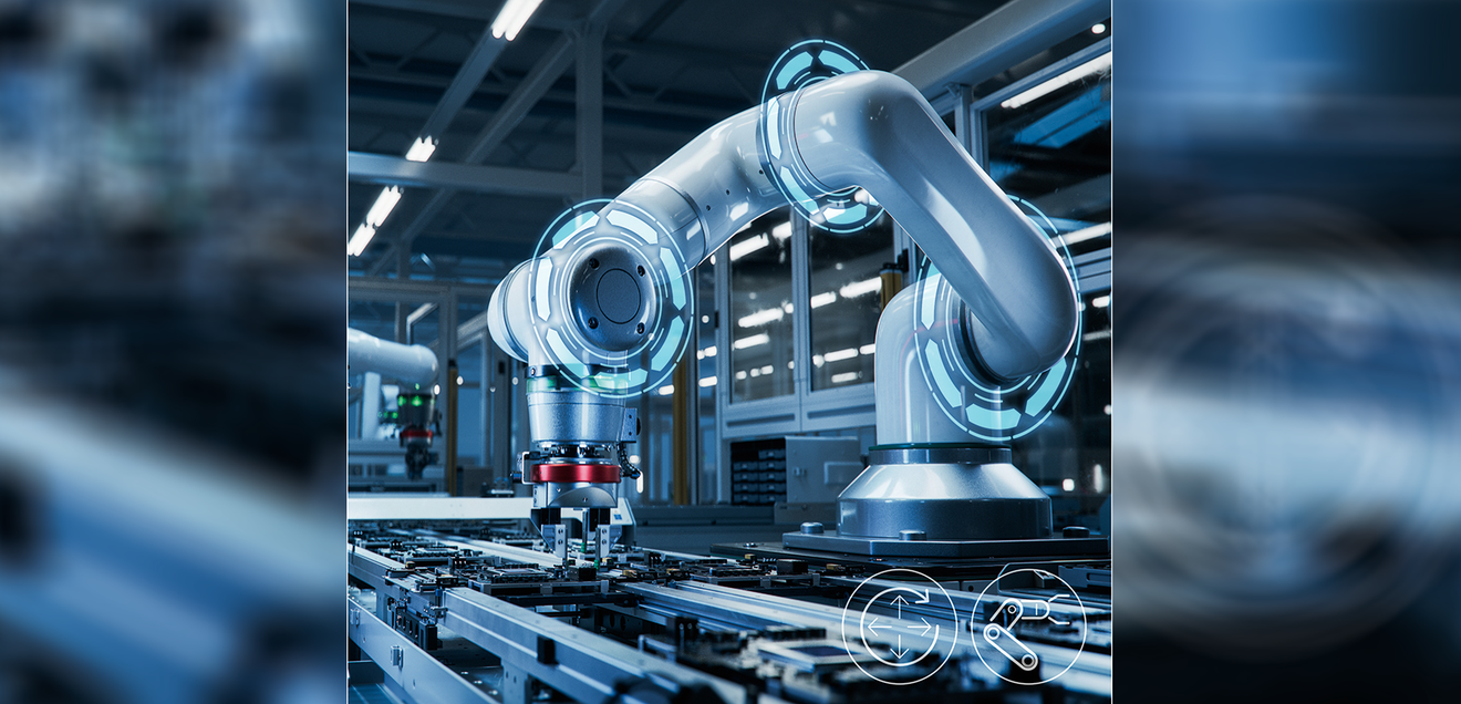
The article introduces a new driver for Trinamic Motor Controller (TMC) and describes the integration of the components into a Robot Operating System (ROS) ecosystem. The TMC-ROS1 driver enables seamless communication between the driver layer of the TMC and the application layer within the ROS framework. This applies to the entire range of TMC boards supported by the driver. The capabilities of the TMC-ROS1 driver are described in detail below, namely motor control, information readout, command execution, parameter readout and support for different configurations. In addition, an overview is given of how the motor controllers can be integrated into embedded systems and applications using the advantages offered by the ROS framework.
The TMC-ROS1 driver
ROS is a robotics middleware containing a set of software libraries and powerful developer tools from drivers to state-of-the-art algorithms—upon which robotic systems or applications can be developed. ADI Trinamic motor controllers enable a new class of intelligent actuators and as ROS became more and more prevalent, especially in robotics, additional module support such as ROS drivers were developed to extend usability for manufacturing and industrial automation applications. Analog Devices’ TMC ROS1 driver provides a functionality similar to the company’s Triaminic Motor Control Language Integrated Development Environment (TMCL-IDE), but with a key distinction: it allows nodes within a ROS-capable system to use TMCs without the need for additional driver installations. Moreover, adi_tmcl incorporates its own TMCL protocol interpreter, enabling it to interpret user-requested commands that comply with the TMCL standard. The final layer, tmcl_ros_node, establishes a direct interface with the ROS system, offering features like publishers, subscribers, and services. Each of these functionalities can be customized using a set of parameters, which will be discussed in detail in the following sections.
Support for different TMC boards
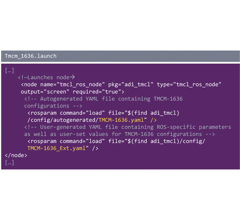
TMC ROS driver or adi_tmcl was designed to support all commercially available TMCs that adhere to the TMCL protocol. As of the publication of this article, it currently supports the CAN interface (specifically SocketCAN). However, there are ongoing developments to include support for other interfaces in the near future. These TMCs encompass the ADI Trinamic PANdriveTM smart motors and modules, which can further be categorized for stepper motors and brushless DC (BLDC) motors. The use of ROS parameters enables adi_tmcl to seamlessly support different TMC boards. This allows the configuration of the tmcl_ros_node without the need to rebuild the entire package(Figure 1).
Within the adi_tmcl/config directory, each ADI Trinamic motor controller module (TMCM) is associated with two YAML files. These files, written in a human-readable data serialization language, contain ROS parameters and should be loaded during execution:
- adi_tmcl/config/autogenerated/TMCM-XXXX.yaml - This YAML file is autogenerated and contains module-specific parameters and is not recommended to be modified as it may cause the node to performdifferently.
- adi_tmcl/config/TMCM-XXXX_Ext.yaml - This YAML file contains all parameters that users can modify to (1) communcate with the board (for example, interface name), (2) enable control of motors, and (3) change ROS topic names
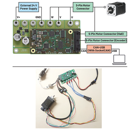
For example, to use the 'TMCM-1636'(Fig. 2), all you have to do is start adi_tmcl tmcm_1636.launch using $ roslaunch. The YAML files for the TMCM-1636 are loaded with adi_tmcl/launch/tmcm_1636.launch.
One-time configuration of TMC modules using the TMCL IDE
Before using the TMC board via ROS, the board needs to be calibrated with the motors being used. All calibration should be done using the TMCL-IDE and should be stored in the EEPROM (otherwise the motors may not be controlled correctly).
- For a run-through/tutorial of how the motor calibration is done in the TMCL-IDE via its Wizard Pool feature,
• For BLDC motor modules like TMCM-1636, check this tutorial.
• For stepper motor modules like TMCM-1260, check this tutorial. - For a run-through/tutorial of how the proportional-integral (PI) tuning is done in the TMCL-IDE via its PI tuning feature, check this tutorial.
Once calibration and tuning have been completed, all parameters must be saved in the board's EEPROM. This can be done either with the store parameter, the STAP command and/or creating and uploading a TMCL program and activating the autostart mode. Some boards do not support all of these three options.
After the configuration/tuning of the TMC and motor, the design of the TMC ROS driver was simplified to control the motors based on the one-time configuration using TMCL-IDE.
Moving and stopping the motor
The TMC ROS driver moves or stops the motor by publishing in one of the following topics:
- /cmd_vel (geometry_msgs/Twist) - Sets the motor’s velocity
- /cmd_abspos (std_msgs/Int32) - Sets the motor’s absolute position
- /cmd_relpos (std_msgs/Int32) - Sets the motor’s relative position
- /cmd_trq (std_msgs/Int32) - Sets the motor’s torque
It should be noted that in a TMC configuration with multiple axes, there are separate topics for the different motors.
Users can connect their ROS systems to publish in these specific topics to control the movement of the motors. The choice of topics depends on the application, the TMC settings and the motor types used. For a mobile robot, for example, the user can choose to set the speed, whereas for a gripper it would make more sense to specify the position.
Users can connect their ROS systems to publish to these specific topics, enabling them to control the movement of the motors. The choice of topic depends on the particular application, TMC settings, and the type of motors being used. For instance, in the case of a wheeled robot, the user might choose to set the velocity, while for a gripper, setting the position would be more appropriate.
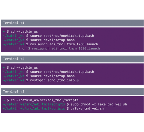
As an illustrative example, consider the script adi_tmcl/scripts/fake_cmd_vel.sh. This straightforward script orchestrates the rotation of a motor in both clockwise and counter-clockwise directions, progressively increasing the velocity. The commands shown in Figure 3 are used for execution.
Reading information from TMC and engine
The system can read information from the TMC ROS driver by subscribing to the /tmc_info (adi_tmcl/TmcInfo) topic. This provides data on voltage, TMC status, actual speed, actual position and actual torque.
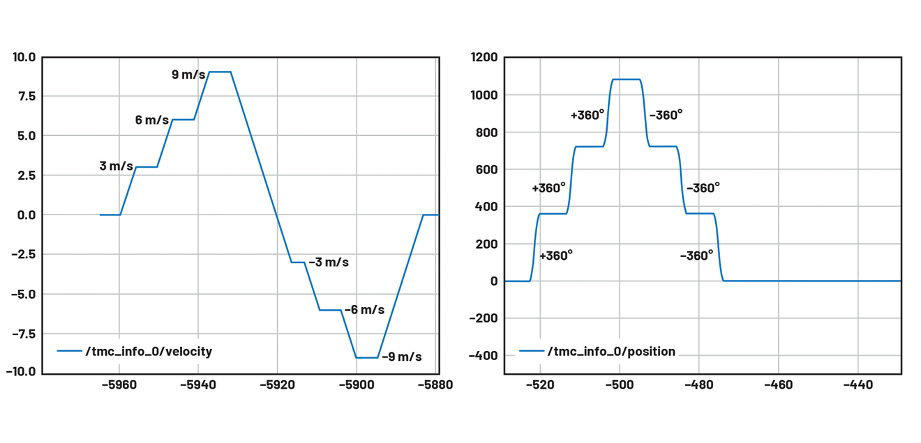
Users can link their ROS systems to subscribe to these designated topics. This allows them to monitor and potentially take action based on the parameter values. For instance, in application-specific scenarios, one might choose to halt the system upon detecting errors in the TMC status or execute a preprogrammed action once the motor reaches a specific position. Figure 4 shows an example of reading the actual position and the actual speed from the TMC (/tmc_info_0).
Execution of user-specific TMC commands
The tmcl_custom_cmd (adi_tmcl/TmcCustomCmd) feature makes it possible to access and customize TMC parameters. This allows values from the axis parameters (APs) as well as the global parameters (GPs) of the TMC to be read and set in a targeted manner.
Users can integrate this service into their ROS systems to meet specific application requirements. This functionality allows the TMC board to be configured directly from the ROS driver. For example, a user can use the Set Axis Parameter (SAP) command for the maximum current to set the maximum permissible current. However, users should know exactly which parameters they are modifying using this feature, as incorrect values can cause the TMC ROS driver to fail.
Access to the values of all axis parameters
The system can use the command tmcl_gap (adi_tmcl/TmcGapGgpAll) to access the values of the axis parameters (APs) of all TMCs. It is possible to read out specific values for specific motors or axes.
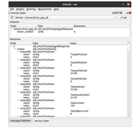
Users can integrate their ROS systems with this functionality to meet the individual requirements of their application. Among other things, this service can capture the current settings and status of the TMC board, including APs such as encoder steps, PI tuning, commutation mode, etc.(Figure 5).
Access to all global parameter values
The command tmcl_ggp (adi_tmcl/TmcGapGgpAll) enables access to all global parameter values (GPs) of the TMC, whereby a comprehensive query of the global configurations can be realized. This function allows the current configurations and status values of the TMC board to be read out. The GPs that can be accessed in this way include the CAN bit rate, the serial baud rate, the autostart mode, etc.
Configurations with multiple TMC boards
For larger systems such as robotic arms that require multiple TMC boards, the TMC-ROS driver allows multiple configurations.
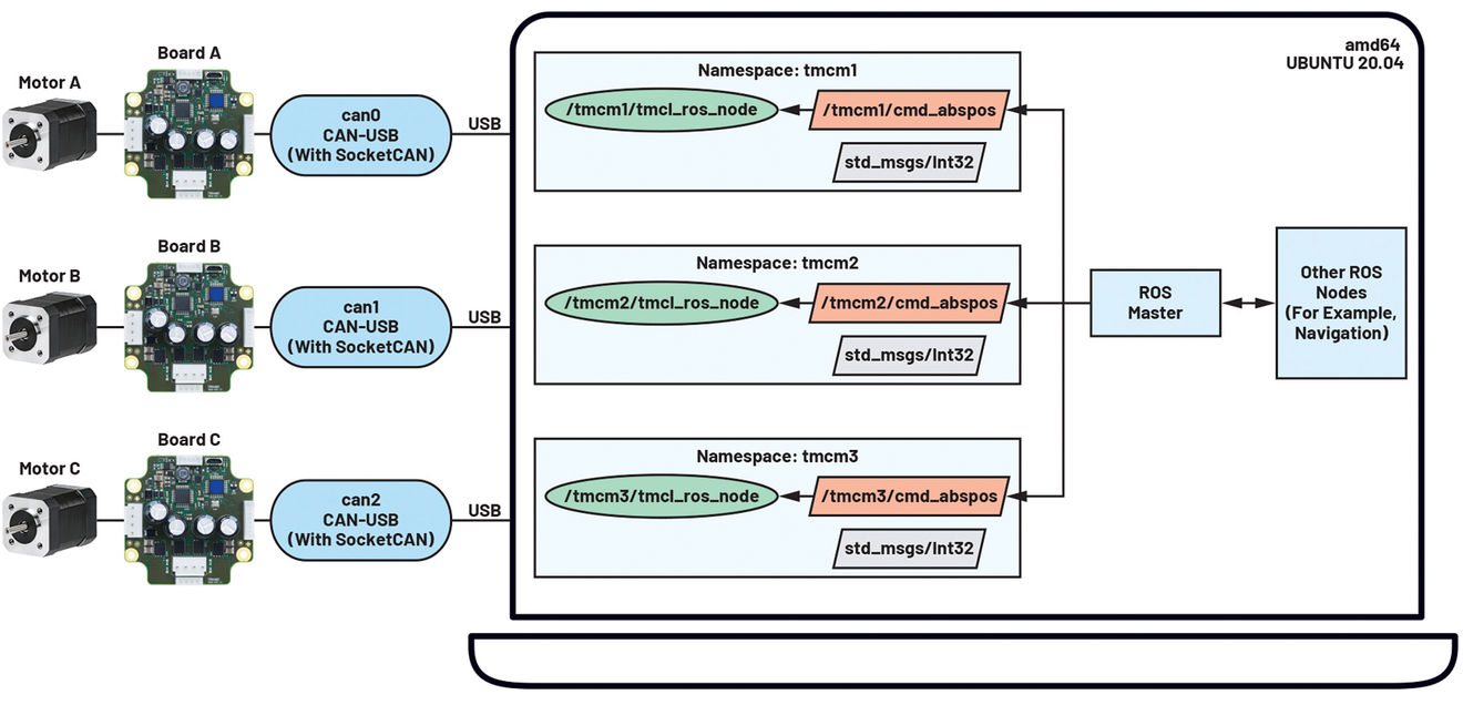
- Multiple TMC boards in multiple CAN channels: If a user has one CAN-USB for each TMC board, namespaces are added(Figure 6) to distinguish the instance of each node. In this particular use case, the parameter comm_interface_name must be updated accordingly to ensure correct communication with the board.
- Several TMC boards in one and the same CAN channel: As Figure 7 shows, the operation of multiple TMC boards in one and the same CAN channel is also supported by the TMC-ROS driver. As with the support for multiple TMC boards described above, namespaces have also been introduced here in order to differentiate between the various node instances. While comm_interface_name is retained for all boards, comm_tx_id and comm_rx_id are adapted to ensure proper communication with each board.
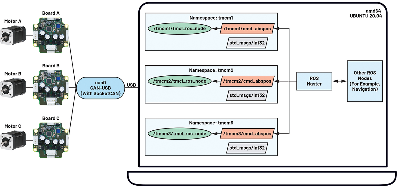
In these two configurations, motor A can be controlled by publishing to /tmcm1/cmd_abspos, motor B by publishing to /tmcm2/cmd_abspos and motor C by publishing to /tmcm3/cmd_abspos.
Easy integration into ROS systems and applications
The message transfer system offered by ROS makes it easy to exchange nodes, such as drivers or algorithms, in larger systems. With the development of the TMC ROS driver, this advantage is also extended to TMC boards, enabling seamless integration into ROS systems and applications.
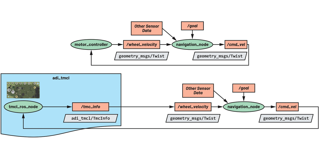
- Integration in AGVs and AMRs: Figure 8 illustrates how a navigation_node can control a mobile robot by sending /cmd_vel in the format geometry_msg/Twist. The motor_controller then provides feedback via /wheel_velocity in the format geometry_msg/Twist, whereupon the navigation_node can perform a corresponding recalibration. Based on the knowledge of where the navigation_node publishes and subscribes, the motor_controller can easily be changed by the tmcl_ros_node. Similar to the function for reading information from the TMC, adi_tmcl publishes real-time information about the wheel speed, and the wheel_velocity_node transforms the wheel speed information from adi_tmcl/TmcInfo into geometry_msg/Twist. Since the new architecture and the TMC board integrated into it adhere to the correct data formats, the mobile robot should function unchanged.
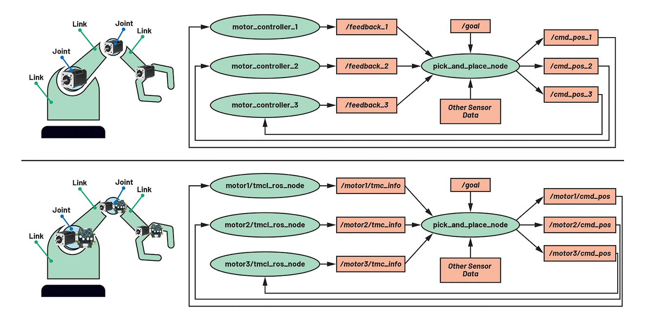
- Integration into robotic arms: For the integration of TMC boards into a pick-and-place application with a robotic arm, Figure 9 illustrates how multiple motors are required to move the arm. Similar to the use case described above, the user must ensure that pick_and_place_node subscribes to or publishes the expected data format.
A step-by-step guide on how to integrate TMC boards into ROS systems and how to use the features just described can be found here. Further information can also be found in the original article, which contains more code sections and an example of the use of stepper motor modules.
ADI's TMC ROS driver enables seamless communication between the underlying TMC driver layer and the application layer in a ROS-managed system. This advantage comes into play with a whole range of supported TMC boards.
The authors

Krizelle Paulene Apostol is a software systems engineer and works at the Philippine Development Center, which is part of Analog Devices' Sensing, Motion, and Robotics Group.

Jamila Aria Macagba is a Senior Software Systems Engineer at the Philippine Development Center, which is part of Analog Devices' Sensing, Motion, and Robotics Group.

Maggie Maralit is a Software Systems Design Engineering Manager at the Philippine Development Center, which is part of Analog Devices' Sensing, Motion, and Robotics Group.


You might also be interested in
Modularized EMS Automation with ASi-5
With 'EMS modular with ASi-5', SEW-Eurodrive is expanding its 'Movi-C' modular automation system to include an automation solution for electrified monorail systems.
 read more...
Strategic Minority Interest in Synapticon
The Swiss Maxon Group is expanding its expertise in the field of motion control through a strategic partnership with the German company Synapticon. The aim of the collaboration is the joint development of high-performance drive solutions with...
read more...The MicroPlyer Microstep Interpolator
Some Trinamic components are equipped with MicroPlyer technology. This interpolation technique allows existing systems with low microstep resolution to be upgraded to a higher resolution without modifying the motion control logic.
read more...International network expanded
With the complete takeover of EME Motor 2008, S.L., Mayr Antriebstechnik now has its own subsidiary in Spain.
read more...Preparation for business picking up
Bosch Rexroth closed the 2024 financial year in a difficult market environment with significantly lower sales than in the two very strong previous years. Sales in 2024 amounted to around 6.5 billion euros. That is 13.6 percent less than in 2023.
read more...Stephan Schech is Managing Director for the GSA Region
The specialist in motion control and positioning systems, Aerotech, has announced new leadership: Stephan Schech has been appointed as the new Managing Director to further strengthen and expand the company’s presence in the GSA region.
read more...New Vice President of Sustainability
Rockwell Automation has appointed Emmanuel Guilhamon as Vice President, Sustainability, effective July 1. Guilhamon will report to Becky House, Senior Vice President, Chief People and Legal Officer.
read more...TSN/A Conference 2025 | September 24, 11:30...
IEEE TSN Stream Configuration in UAFX Connection Manager
This talk elaborates on the OPC UA FX adoption of IEEE TSN as a transport layer, reflecting on UAFX integration of the CNC/CUC concept and network configuration.
read more...TSN/A Conference 2025 | September 24, 02:30...
IEEE TSN and Industrial Ethernet adoption challenges
It becomes evident that TSN adoption will happen over a period of time where new technology will coexist with legacy Ethernets and fieldbuses.We would like to challenge the existing testbeds, plugfests, and IA vendors with accommodating the missing...
read more...